The necessity of switch size resistance modelling for high switching frequency applications
Switch size resistance modelling refers to the use of a small resistor to model the closed switch and a large resistor to model the open switch; this method is the classic switch modelling method used in offline electromagnetic transient simulation software. For the large and small resistor modelling method, the corresponding resistor values are switched when the switch state changes, so that when the switches in the power electronic converter bridge are frequently turned on and off, the conductance matrix of the system is constantly changing; this is very challenging for the implementation of FPGA-based simulation.
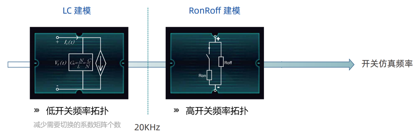
The classical switching LC modelling approach has a very good advantage that no matter how the switching state changes, only the injection current calculation changes, and the system admittance matrix remains unchanged. However, the limitation is that since the switch is modelled with an energy storage element (inductor or capacitor), the energy stored in the inductor or capacitor is easily lost when the switching state is switched, resulting in spurious power loss. When the switching frequency is less than 20kHz, in general, the switching loss can be reduced with a better setting of Gs and the switch-off initial voltage (Vs_off_init), and a better simulation result can be achieved. However, for PWM frequencies higher than 20kHz, it is often difficult to achieve good results with LC modelling.
For this reason, ModelingTech has introduced a hybrid simulation method of RonRoff and LC modelling. For low switching frequency topologies, users can use LC modelling; however, for high switching frequency applications, users can choose the RonRoff modelling method to achieve better simulation results.
Example of an active filter at 50kHz
The following active filter system has a diode rectifier bridge (as a non-linear load) and an IGBT converter bridge, the IGBT converter bridge is used to generate a compensating current to make the grid current harmonic less (waveform close to sinusoidal). the high switching frequency of the IGBTB is favourable to obtain good filtering. In this example system, the converter bridge operates at a switching frequency of 50 kHz.
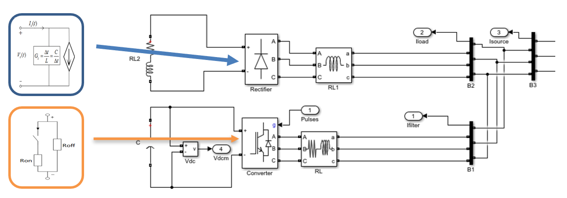
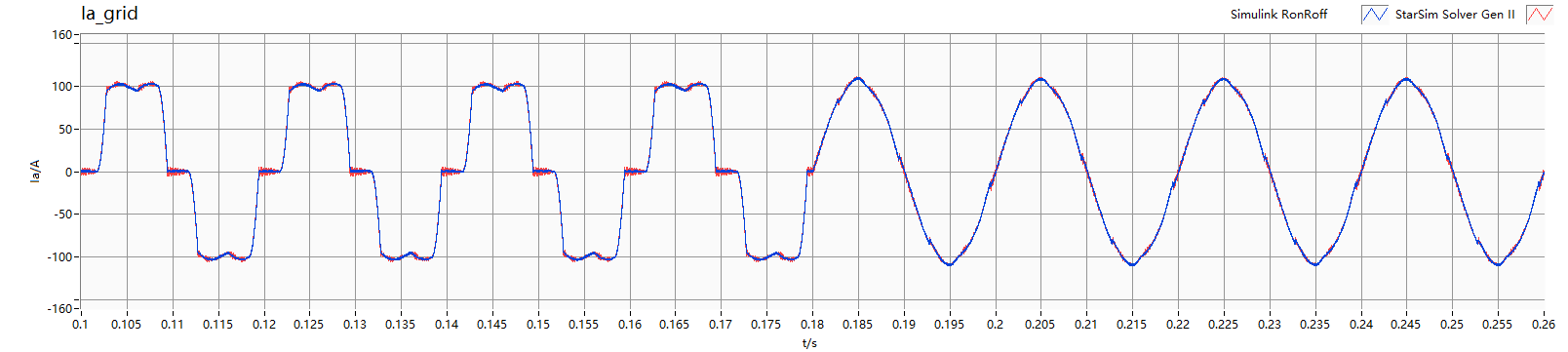
For this system we used a hybrid RonRoff and LC modelling approach, with the diode bridge modelled by LC and the IGBT converter bridge modelled by RonRoff. The following figure shows the comparison between the hybrid modelling approach and the Simulink simulation results, the blue one is the Simulink offline simulation results, and the red one is the RonRoff and LC hybrid modelling simulation results. The left part of the figure shows that the grid current is a nonlinear diode rectifier waveform when the IGBT converter bridge has not yet generated the compensation current; the right part of the figure shows that when the IGBT converter bridge starts to generate the compensation current, the waveform of the grid current becomes better and tends to be sinusoidal; it can be seen that the red and blue curves overlap very well, which verifies the validity and accuracy of the hybrid modelling method.


 Technology

 User Cases